
|
FAQ |
|
|
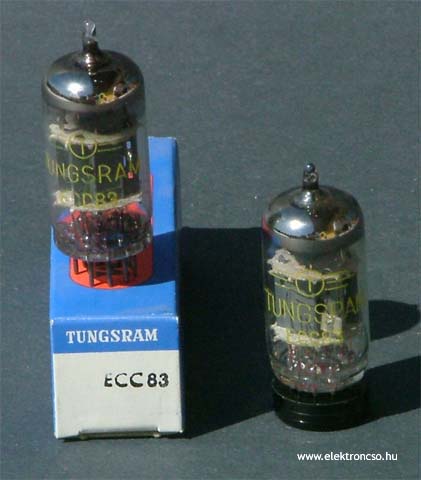
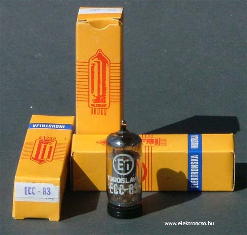
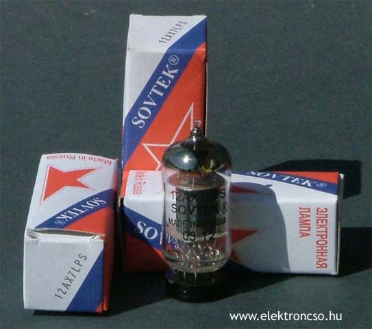
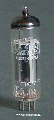
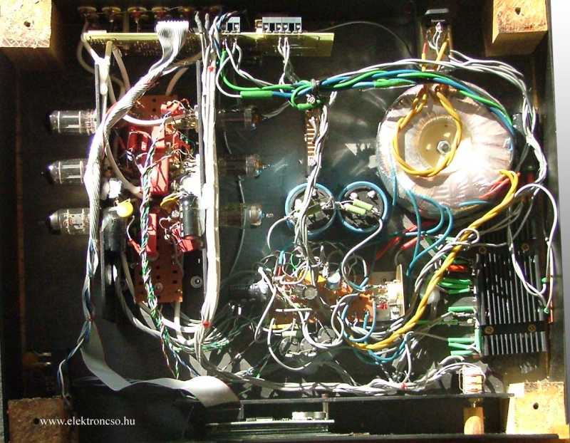
The most important part of the GADP02 pre-amplifier is the passive RC RIAA network (the RIAA is the abbreviation for “Recording Industry Association of America” and is the standard for equalization of microgroove records). According to the published descriptions/schematics it is possible to build a better sounding “passive” RIAA network what uses inductors too (LRC network), but making the correct inductors would require a huge job and the result still could be unpredictable. Passive RC means that the RIAA network is between 2 stages and not in the negative feedback loop. The next requirement was that the whole phono amplifier had to be without any feedback loop. Since the power amplifier is also free from any negative feedback loop - why would I diminish the sound of the power amplifier with a RIAA pre-amplifier with feedback? The signal – coming from the MC or MM pick ups– is accommodated by a 47kΩ resistor, what gives ideal load to these pick-ups. If we want to use a classical MC pick-up, we need to use either one pre-stage or one MC transformer. The necessary amplification of the incoming signal is realized by grounded triode (classical topology), concretely by one 1 half of 12AX7 (ECC83). The passive RC RIAA network is driven by a cathode follower (2nd half of the 12AX7 (ECC83)) what ideally has low output resistance. The voltage loss across the RIAA network is amplified by 1 half of cathode grounded 12AX7. This cathode follower drives directly another cathode follower what gives the output (2nd half of this 12AX7) through the C2 capacitor. The output of the RIAA pre-amplifier goes to the input selector together with other line level inputs, i.e. radio, recorder, CD player, etc. In the GADGET P02 pre-amplifier the input selector is made by set of relays - these relays use silver contacts. This microcontroller provides also the following functions: monitoring function of the recording device, information about the chosen input/function (display function), and the delayed switching of the input anode. The signal from the input selector goes to the volume pot-meter and to the line amplifier. The output of this line amplifier is the global output of the whole pre-amplifier. The selected ALPS potentiometer fulfills the requirements of the pre-amplifier and gives very good quality for a reasonable price. Sure it is not the top black ALPS, but the top black ALPS pot-meter was highly above the acceptable price. The chosen potentiometer guaranties more than 10.000 turns without any noises and also ensures good parallel running of the 2 channels. One extra specialty of this potentiometer is that it has a push/pull switch on its axes, what gives the possibility to drive the microcontroller. Thus, the manipulation of the whole pre-amplifier is done by one pot-meter: pushing in the axes of the potentiometer controls the input selection function, pulling the axe of the pot-meter out gives the possibility to control the brightness of the display, and also can control the monitoring function of the recording device. The line amplifier is build from grounded cathode triode and from direct connected cathode follower (the topology is similar to the topology used in the vinyl stage). The used tube in the line amplifier is the 12AU7 (ECC 82). This solution (no use of the SRPP) gave me very good sounding pre-amplifier, against to the solutions using SRPP. In the GADGET series the power amplifier uses SRPP. Using the SRPP in the pre-amplifier would give more bell type of sound, what could be too much in combination with the power amplifier. We have to be very careful during the building process of this pre-amplifier. I have never used PCBs for building tube amplifiers. When I was building this pre-amplifier I have red an article what described why the use of the PCB is not good either in HIFI amplifiers either in tube amplifiers. The article (published in the nineties!) pointed out that the acids (used during the etching process of the PCB) are never fully removed from the PCBs and the etching can go on in a given humidity. The article suggested that after etching the PCB has to be washed in 4-5 baths and later “baked” in an oven. Next, varnish has to be applied to the PCB to protect the PCB from the environment. The tube amplifier makes this even worst because the driving of the tubes does not need any power. Therefore, the disturbances (due to the above described facts) can easily get into the signal path, and later by amplification they can be heard from the speakers. Thus, this article influenced me and I did not use PCBs. Instead I use soldering stabs what was used in old televisions and old radios. Note: For curiosity I like to mention that the “white ear” listeners like more the bakelite PCBs compared to the expensive Teflon PCBs. There is also a difference between one sided and 2 sided PCBs. In this pre-amplifier I have used PCB only for the microcontroller as this can be seen on the attached photo. If we use such an air-type assembly, we have to make sure that the components are fixed not only electrically, but also mechanically. During transportation some capacitors can became loose due to their significant weights. For this purpose I sue the hot glue to “fix” these components. This makes it possible – if necessary - to remove/modify the components. The pre-amplifier is very sensitive for building mistakes and disturbances. The grounding has to be done according to the schematics, and the ground should be done only on the indicated places! During the building of the pre-amplifier I have tried many power supplies because I wanted to have a very low brum and noise level. The most recommended power supply is the PSU from Hiraga’s pre-amplifier. This is fully passive, built only from LRC components. Unfortunately, I did not get good result from this PSU. This PSU also needs quite a big space, rather high voltage. In the original schematics the 6X4 diode is used. I also can recommend this diode, however – unless it is requested by the client - I use semiconductor based FET PSU. If the FET power supply is used, I recommend the implementation of the parallel PSU, what is known as a softer sounding PSU. If somebody has time and budget, he can build the 6S19P (6С19П) tube based tube stabilizator, and surely he will not be disappointed. Many well known firms use this kind of PSU. Myself - because of the power supply war - I have turned towards using accumulator based power supply, but this is described in another article. I wish a good luck for this pre-amplifier builder. I have built this GADP02 pre-amplifier several times and I have got always nice results. Often I was asked to build the pre-amplifier without the vinyl stage (because the client did not have an LP player in his setups). The advantage of the topology is that it minimizes the use of capacitors in the signals path, what on one had is interesting from budget point of view too and on the other hand it improves the sound, and it is still it is not DC coupled pre-amplifier. |